Here's the Tina2 print head assembly (or "hotend" – because it gets hot to melt the filament) constituent parts. There is a useful explanation here:
https://www.xometry.com/resources/3d-printing/hotend/
Note the inductive proximity sensor (1) has been stripped out of the umbilical cable (2):
.

- Tina2Anatomy-01-small.jpg (248.17 KiB) Viewed 6766 times
- Inductive Proximity Sensor, LJ12A3-4-Z/BX (note the OEM part has an orange tip, not blue)
- Umbilical Cable
- Fan, 30x30x10mm 12V
- Heater Block + Thermocouple
- Nozzle
- Heater Block Mounting Tube
- Heat Sink
- Feed Tube Push-In Fitting
- Frame
- Sensor Mount
- Frame Screws, 2mm hex pan head, 2-off
- Sensor Screws, 2.5mm hex pan head, 2-off
- Hotend Screws, 2.5mm hex cap head, 4-off
- Heater Block Mounting Tube Grub Screw, 2mm hex
- Sensor Mount Screws, 2mm hex countersunk head, 2-off
- Bowden Feed Tube, PTFE 2mm ID, 4mm OD, 0.5m
- Umbilical Anchor
The connectors appear to be JST XH type (fan 2-way, sensor 3-way, heater block + thermocouple 4-way). The JST XH spec is 2.50mm pitch, but several suppliers of supposedly "JST XH" connectors say 2.54mm pitch. However, the difference between 2.50 and 2.54 over 4 pins is too minor to make a difference, and I have found they fit regardless. (Note the most difficult part of fitting these connectors is crimping the contacts to the wires reliably, and I have had to resort to soldering.)
Duct
The fan blows through the heat sink, then a duct built into the X carriage directs the air onto the print:
.

- Tina2Anatomy-02-small.jpg (241.82 KiB) Viewed 6766 times
.
Disassembly
It is assumed the finger guard is not present (as per the photos). The guard is a perforated metal shield fitted across the X gantry to prevent accidental contact with moving or hot parts, which is appropriate for children and casual users but impedes the view and access for serious users. The guard is secured by two screws on top of the X gantry (one at each end) – remove these and then unclip the guard.
[Tina2S: the guard is a small perforated plate attached to the hot-end itself, and not necessary to remove separately from hot-end disassembly.]
Before proceeding, note that reassembly will require a selection of cable ties to replace those which are cut during disassembly.
1. Prior to disassembly, unload the filament. If the filament cannot be unloaded, cut it immediately below the extruder (ie the motorised feeder on the side of the Tina2). Disconnect the power supply and ensure the printer has been off long enough for the heater block to have cooled down.
2. Externally, release the Bowden feed tube (16) from the extruder by pressing the ring down on the push-in fitting and pulling out the tube. If there is filament loaded, release the feed roller while doing this so the cut end of the filament comes with the feed tube.
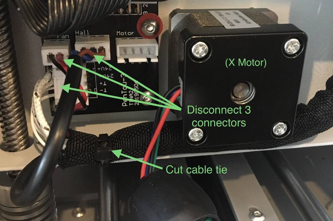
3. From the rear of the X carriage: cut the cable tie securing the umbilical and disconnect three connectors. The connectors are retained by friction latches, but do not require much effort to disconnect. Pull the umbilical away from under the X motor.
[There may also be another cable tie further along the umbilical, where it passes over the X carriage (see here: viewtopic.php?p=1293#p1293). If so, remove it and do not refit as it creates further unnecessary strain when the umbilical flexes.]
(In the photo, the X motor cable has been disconnected to aid visibility)
.
- Tina2Anatomy-03-small.jpg (247.33 KiB) Viewed 6766 times
.
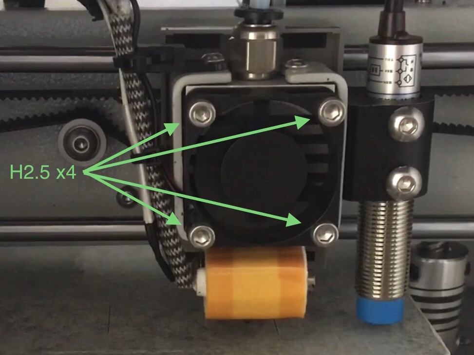
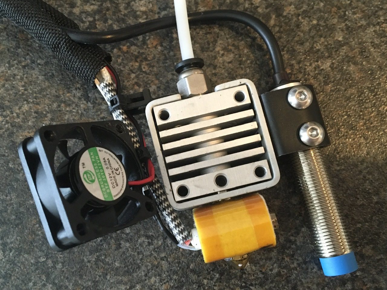
4. From the front: remove the hotend screws (13). The print head assembly is now free to remove from the Tina2. Note that the fan (3) is only secured by the same screws, and the wires to the fan may be fragile.
.
- Tina2Anatomy-04.jpeg (141.17 KiB) Viewed 6766 times
.
- Tina2Anatomy-05-small.jpg (247.83 KiB) Viewed 6766 times
.
5. Cut the cable tie securing the umbilical to the anchor (17). Take care not to strain the wires to the heater block (4) hereafter.
6. Remove the sensor screws (12), and strip the sensor cable out of the umbilical sheath. The sensor is now free.
7. Cut the cable tie securing the fan (3), and strip the fan cable out of the umbilical sheath. The fan is now free.
8. The push-in fitting (8) unscrews from the heat sink (7), and the feed tube (16)releases from the fitting by pressing the securing ring.
9. Remove the heater block mounting tube grub screw (14) from the heat sink (7), located in the centre immediately above the heater block (4). The heat sink etc will now separate from the heater block. This might be difficult if there is melted filament gluing it together, or remaining filament might come away with the heater block.
[Tina2S: the heater block is fitted with an intermediate connector, so the block can be detached from the umbilical without stripping the cable out of the umbilical. There is also a silicone "sock" fitted to the heater block, which is easily removed (instead of the permanently-fitted insulation on the Tina2 heater block).]
10. The heater block mounting tube (6) unscrews from the heater block (4). There are flats machined into the tube just above the heater block to enable grip with pliers or a spanner.
11. The nozzle (5) unscrews from the heater block (4). This may be extremely difficult unless the heater block is hot, which both melts any filament and loosens the nozzle by differential expansion. The block can be heated by plugging it (separately) into its port on the rear of the X carriage, powering up the printer and running a filament unload operation. Ensure the block is on a heat-proof surface, and take care when handling. I advise not removing the nozzle unless absolutely necessary, which can be best achieved while the Tina2 is assembled (minus the carriage guard).
12. The umbilical anchor (17) is removed from the heat sink (7) by removing one of the frame screws (11).
13. The frame (9) is removed from the heat sink (7) by removing the other frame screw (11). This is only possible once the heater block mounting tube (6) has been removed from the heat sink (7), step 9, and the umbilical anchor has been removed, step 12.
14. The sensor mount (10) is removed from the frame (9) by removing the two sensor mount screws (15) from inside the frame. This is only possible once the frame has been removed from the heat sink (7), step 13.
Assembly & What To Watch For
Assemble in reverse order of disassembly.
The mounting tube (6) and nozzle (5) must be very tight in the heater block (4), otherwise melted filament will find its way through the threads and then onto the print-in-progress, ruining it. In my experience, the nozzle cannot be tightened adequately unless the block is hot – so tighten it once re-assembled and running. Beware of twisting the heater block -
see post 9.
Ensure the Bowden feed tube (16) is clear before assembly, and that it is fitted fully into the heater block mounting tube (6). This is important, because the feed tube provides the heat break between the heated parts and the filament feed, and it is necessary that the filament does not melt before it reaches the nozzle. The heat sink and fan are also important to this.
Ensure the fan wires are routed through their channel in the fan housing, otherwise they can become trapped between the fan and the heatsink, resulting in damage when the fan and heat sink are secured to the carriage.
When reassembling, provided there is sufficient cable on the sensor, I advise securing the sensor cable in a strain-relieving S bend through the sheath and anchor as follows:
.

- Tina2Anatomy-06-small.jpg (240 KiB) Viewed 6766 times
.
Ensure also that the wires to the heater block are not strained, remaining clear of the frame. With the cable tie tight at the anchor, there should be no possibility that the cables get pulled.
 ...but I don't know how long for! I did a "quick repair" rather than a "long-term solution".